
Prepare & launch
Surface handling isolates, prepares and introduces a lift element under controlled conditions.
GAS-LIFT TECHNOLOGY
Our current direction links controlled surface handling, downhole travel, lifted return, recovery and reuse in one connected cycle.
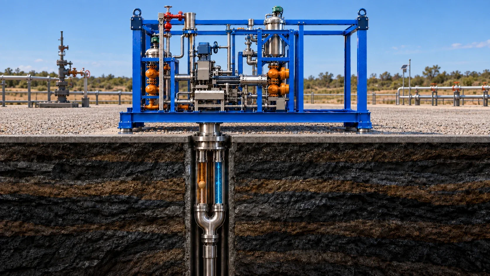
Gas lift is a form of artificial lift used in oilfield production. In conventional gas lift, injected gas reduces the hydrostatic pressure of the fluid column so that available reservoir pressure can move fluids toward the surface.
Golf Gas Lift is NAVI-OIL’s integrated development direction within this wider engineering context. Its public system view distinguishes circulating lift elements, instrumented balls and surface instrumentation. These roles should not be confused with a conventional gas-lift valve installation or assumed to be identical in every application.
Gas-lift definition: SLB Energy GlossaryA controlled surface unit prepares and introduces a lift element into a gas-assisted flow path. It travels downhole through a dedicated route, then supports liquid return through the production path.
At surface, the returning stream is separated and the lift element can be recovered, cleaned, inspected and prepared for another cycle. Instrumentation and controls help the system recognise events and manage each stage.
Surface handling isolates, prepares and introduces a lift element under controlled conditions.
Gas assistance moves the lift element through the designated path.
The returning element helps establish a moving interface for liquid lift.
The surface unit separates the returning stream and recovers the lift element.
Recovered elements are cleaned, checked and routed for another controlled cycle.
SURFACE HANDLING
Separation, inspection and reuse connect the returning flow with the preparation of lift elements.
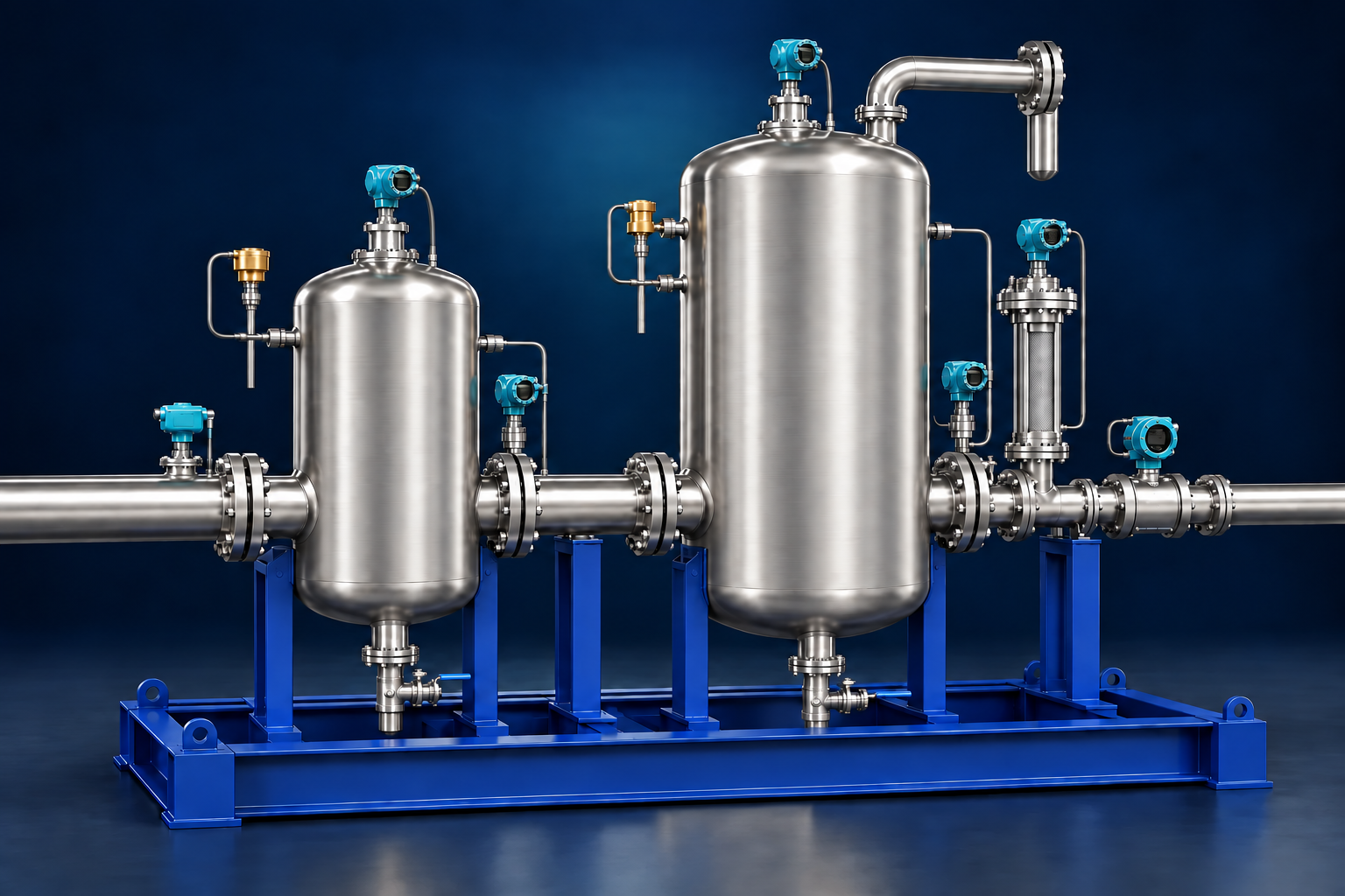
Returning flow connects fluid separation with the recovery of lift elements. Vessel fabrication, sealed connections and instrumentation are part of this surface-handling work.
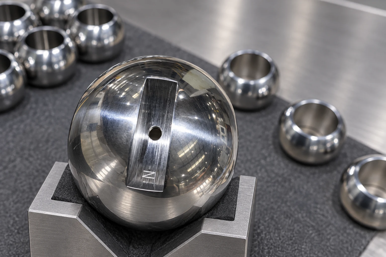
Inspection and reuse planning brings together lighting, imaging, handling and component-condition records. It links the recovered element to preparation for the next cycle.
INTERFACE BEHAVIOUR
A recoverable lift element can meet a local flow passage in different ways. The three states compare clearance, near match and compliant contact.
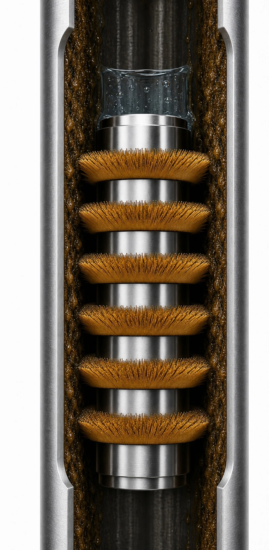
The element envelope is smaller than the local passage, leaving a visible bypass path.
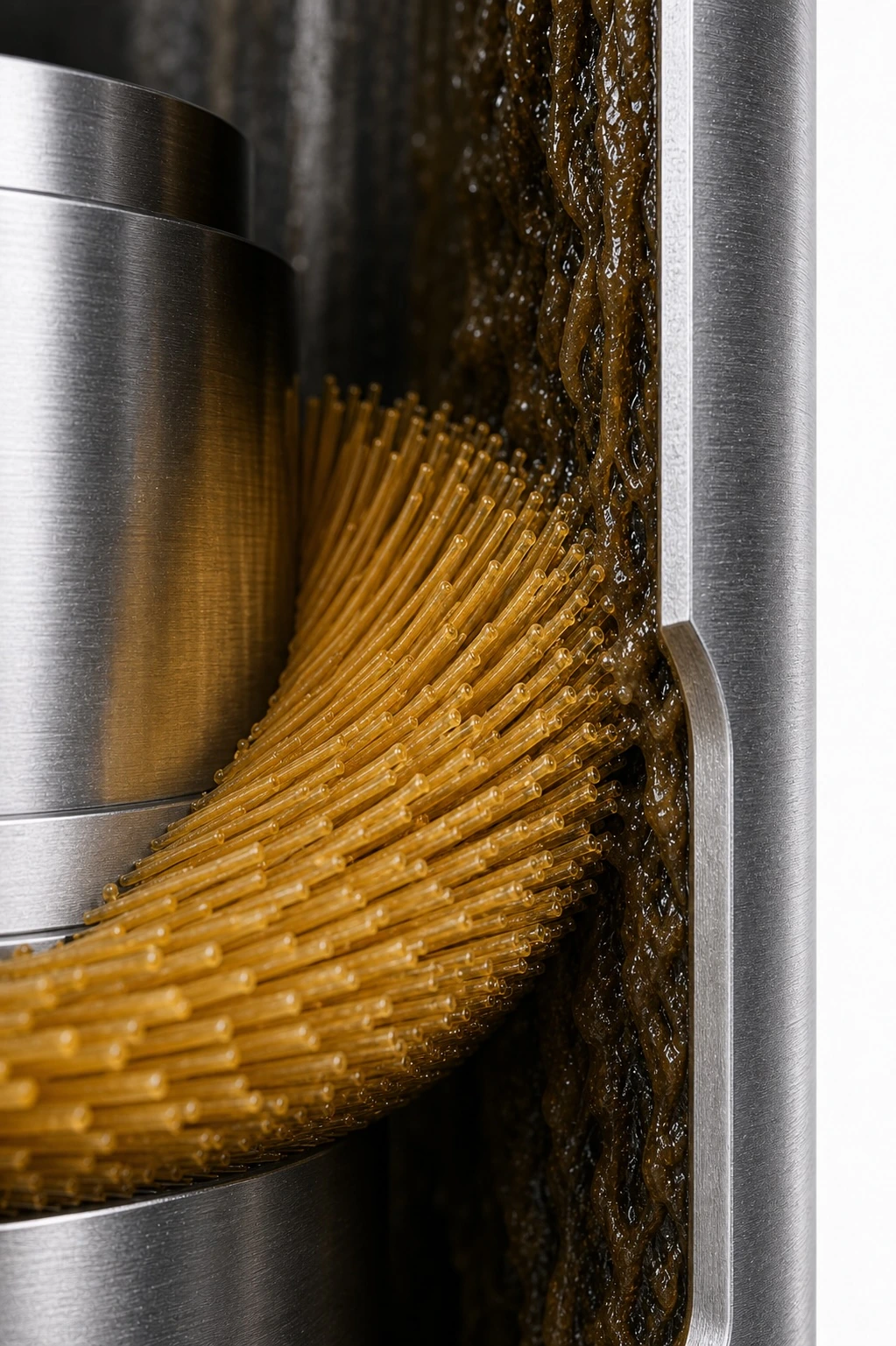
The element and passage are close in scale, creating a transitional contact condition.
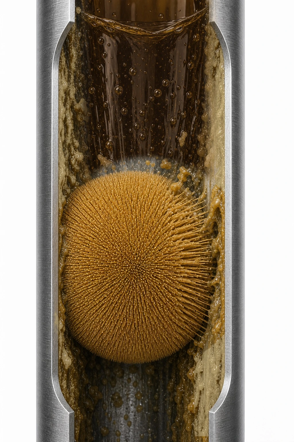
The element envelope is larger and its compliant surface deforms against the wall.
LAUNCH, RETURN & INSPECTION
Identify and prepare the lift element before controlled introduction.
Route the element into the designated travel path.
Separate and receive the returning element at surface.
Record condition and route it for service, reuse or replacement.
SYSTEM ENGINEERING
Our engineering work covers the surface assembly, recovery equipment and instrumentation needed to connect the lift cycle. Each area creates a different set of material, component and manufacturing questions.
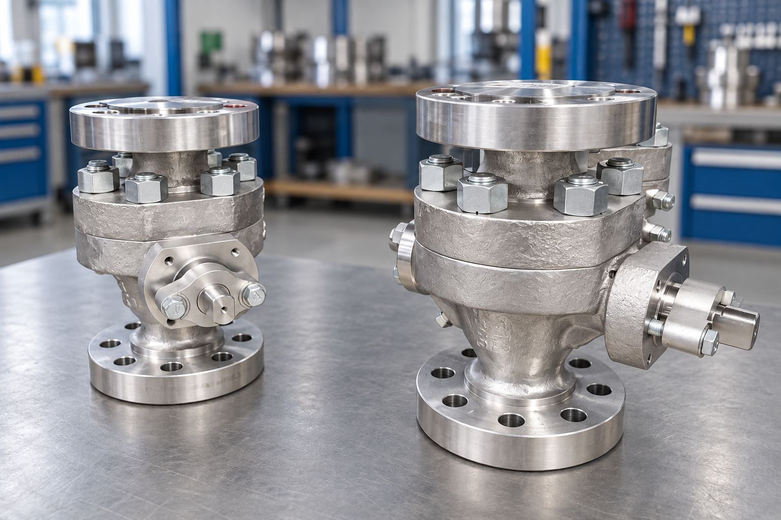
Equipment layouts bring handling assemblies, vessels, pipework and actuated components together. Component selection must account for installation, access and the connections between neighbouring assemblies.
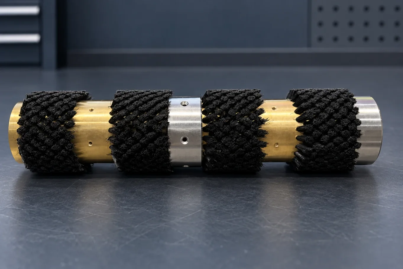
Returning lift elements require recovery, cleaning, inspection and handling. We consider contact materials, wear surfaces and replaceable parts alongside the equipment that moves and services them.
Pressure, temperature and position sensing connect physical equipment with operating information. Mechanical mounting, wiring and signal interfaces need to be considered together.
ENGINEERING WORKFLOW
Mechanical assemblies, sensing hardware, functional checks and control logic are developed as connected workstreams, bringing component-level work into system integration.
SOFTWARE DEVELOPMENT
Our software roadmap centres on equipment status, event records and the handling history of lift elements. Inspection information and maintenance records are also in scope, connecting hardware work with future operating tools.